Home

Battery Monitor Relays, an efficient combination of over/under voltage sensors combined with positive and negative ground detection.
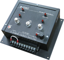
Available with a single relay alarm for any out-of-tolerance condition or with separate relays for voltage and fault conditions.

![]()